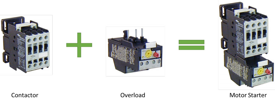
Welcome to a comprehensive guide on choosing the perfect motor starter for your application. Let’s begin with a quick refresher on the key components of a motor starter. Assembled motor starters comprise a NEMA 4X-rated polycarbonate enclosure housing a contactor and overload relay. Get ready to dive into the world of motor starters and make informed decisions!
You may refer to our detailed guide on selecting a contactor to read up on contactors first. Or, if you would like an overview of contactors and overloads and how they work, you may refer to our guide on the basics of motor starters. For pre-assembled starters, we’re only considering non-reversing contactors, and utilization categories AC-3 and AC-4.
How AC Starter Part Numbers Are Built
To get started, it may be useful to explain how the part numbers for AC starters are built:
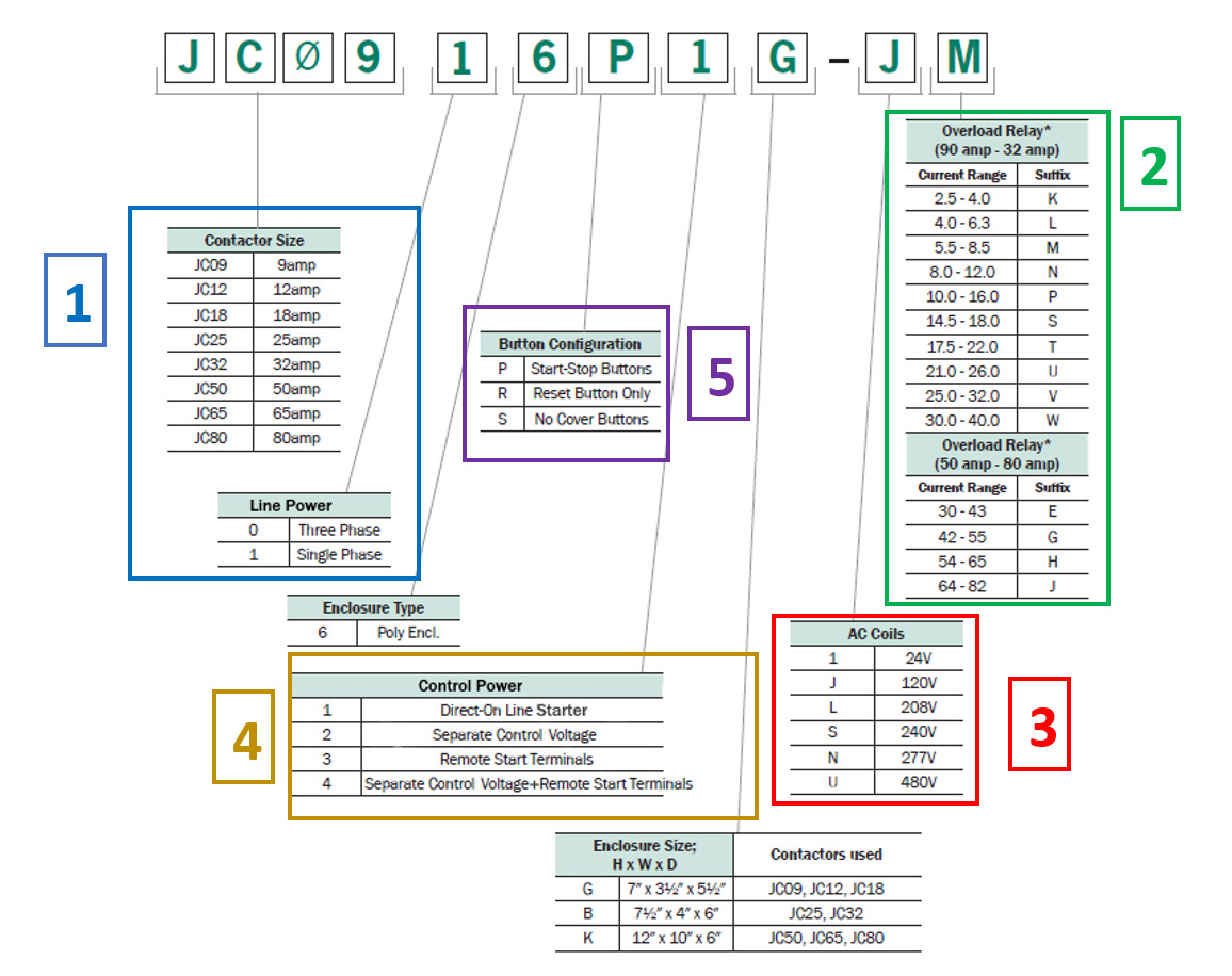
In the above example, the description for part number JC0916P1G-JM is:
Enclosed Motor Starter, Single Phase 9A Contactor, 1ph, direct-online voltage, 4X poly, Start/Stop buttons, 120VAC coil, O/L 5.5-8.5A

Selecting an IEC Motor Starter Step-by-Step
Follow these steps to select the proper motor starter for your requirements:
1. Contactor Size & Line Power
Refer to your motor or equipment nameplate to verify the Full Load Amperage (FLA) at the line power voltage you intend to provide.
Be sure to confirm whether the line power is 1phase or 3phase power to the motor
Choose a starter rated for current (Amps) higher than the FLA of your motor at the line power voltage you intend to use.
2. Overload Relay Range
Choose the overload by selecting a current range that contains the FLA of the motor from step 1
3. AC Coil Control Power
Choose the control power used to close the contactor.
Once you have done this, it should narrow down the starters to those with components suitable for your motor, voltage, and wiring. Then, select your starter configuration based on the following criteria according to your preference:
4. Control Power
If the line power is also used as the control power, wired directly to the contactor, this is referred to as a “direct-online starter”.
If the control voltage is not the same as the line voltage, we refer to this as “separate control voltage”
If the starter needs to be activated from an external switch, we add terminals to accept the control power input from that switch. We refer to this as “remote start terminals”. It is assumed, in this arrangement that the line voltage and control voltage are the same.
If you would like remote start terminals and will be using different voltage for line power and control power, we refer to this as “separate control voltage + remote start terminals”.
5. Enclosure Cover Buttons
Start/Stop buttons give you Green/Red manual buttons for starting and stopping the motor on the enclosure’s cover.
Reset button only gives you a Blue reset button on the enclosure cover to reset the overload relay if it is tripped. The reset button also functions as a local stop button.
There are no cover buttons. (With this option, there is a reset button on the overload itself. However, this is inside the enclosure and requires the enclosure be opened to access it. As a result, the wiring diagram for this option is the same as the reset button only option, the difference is the location of the reset button)
Wiring Diagrams & Selecting a Pre-Assembled Motor Starter
Download the PDF below for wiring diagrams for various configurations. If you are unsure, please feel free to contact us. We are happy to explain further or discuss custom options if you don’t see what you want.
Selecting a Pre-Assembled Motor Starter (PDF)