A disconnect switch is simply an On/Off switch used to cut power to a piece of equipment or electrical enclosure. In some cases, it can be referred to as a “main switch”. According to IEC/EN60204-1: applicable for safety of electrical equipment or machinery a manually operated disconnect switch must be provided for every main power supply. It must include on/off indication (O/I is the international symbol for on/off) with an easily accessible handle for manual operation. It should disconnect all conductors in the off position, and must accommodate a padlock to allow the power to be locked off by an operator. The neutral leg can be disconnected or not. With this criteria in mind, let’s look at the criteria used to specify a disconnect switch for a particular application.
AC vs DC Power
The first step in specifying and selecting a disconnect switch for an application is to determine the power requirements. Different disconnects are used for AC versus DC power. A disconnect made for AC power is not suitable for DC power and vice versa.
Voltage Requirement (Volts)
Springer Controls AC disconnects are all rated for 600VAC, which is consistent with IEC standards. The DC disconnects are rated for up to 1000Vdc. Above these voltages arcing is a larger concern and you’ll need a specialty disconnect.
Current Requirement (Amps)
The contacts in the disconnect switch must be sized to accommodate the current going through them. Higher current requires more robust contacts to avoid overheating, so Springer offers a variety of current ratings to allow the most cost-effective solution to be used. Springer Controls offers AC disconnects from 10A up to 630A. DC disconnects can be supplied rated to 32A at 1000Vdc or rated for 45A for up to 600Vdc.
Mounting
The next consideration is the mounting style. Where and how the switch will be used, as well as the size (current rating) of the switch are all considerations. The most common mounting style is called “4 hole” mounting. This is a simple and effective method for installing a switch to a flat panel, like the door of an enclosure. The base of the switch and the front cover plate sandwich the panel and four screws are used to secure them together to hold the switch in place. A diagram is shown below:
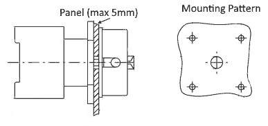
Fig. 1 – Four Hole Mount Diagram
There is also a 2-hole version used for the smaller switches which mounts the same, but uses only 2 holes instead of 4. Additionally, some switches may be “central mounted” through a standard IEC 22.5mm hole or a standard NEMA 30.5mm hole in the panel. In this case, there are no screws, but a threaded plastic nut that secures the switch, handle and face plate to the panel. This mounting style is common for IEC or NEMA pilot devices.
We also offer a variety of base mounted switches. In this case, the switch body is mounted from the back to either a DIN rail or the back panel of an electrical enclosure. Base mounting is more common for larger switches, and when the switch is meant to prevent the enclosure from being opened while power is live. In this case, a shaft connects the base mounted switch to the faceplate and handle mounted to the enclosure door. When the door is closed the shaft fits into a hole on the back of the switch handle. A mechanical lock on the shaft prevents the door from opening while the disconnect switch is in the “on” position, thus ensuring the power is disconnected before the enclosure can be opened. The faceplate and handle are mounted to the panel door via 4 screw holes.
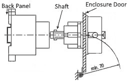
Fig. 2 – Base Mount Disconnect Diagram
Handle
The handle style is highly dependent on the user preference, and the number of padlocks that can be placed on the handle to lock the position. The three most common handle styles are the lever (not lockable), a lockable lever, and a lockable dial. Examples are shown below:
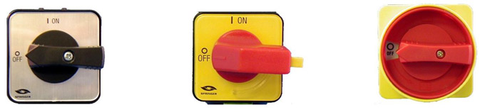
These can be supplied in a variety of colors, but most common is black with silver faceplate/bezel, or red with yellow faceplate/bezel. Custom handles are also available.
To review, the criteria primarily used to specify a disconnect switch are:
- AC or DC Power
- Voltage
- Current
- Mounting style
- Handle style
You should be ready to specify and purchase your disconnect switch!