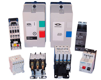
 In previous blog posts, we talked about the differences between IEC vs. NEMA and discussed the basics of a motor starter. Today, we’re going to talk about selecting a contractor for your application requirements. There are 5 primary things to consider when determining how to size a contactor for your application:
1. Full Load Amperage at Line Voltage
The first item to consider is the load, measured in amperes. This load amperage is the amount of current required to power your device at the line voltage.
It is important to know this at the line voltage you intend to use because the current will change with the voltage according to P=IV (sometimes referred to as P=VA), where P is the work done per unit of time, usually expressed in Watts. I (or A) is the electric current in amperes, and V is the voltage. Since P is based on your device’s power requirements, it will remain constant; if you lower the voltage, the current must increase to balance the equation, and vice versa. Generally speaking, with motors and other industrial equipment, you want to look at the nameplate to confirm the input voltage and the Full Load Amperage (FLA).
If you do not have the equipment specifications or nameplate available, the NEC (National Electric Code) has created a contactor sizing chart to help determine the FLA for a given squirrel cage motor size at a given voltage according to IEC standards, and we’ve converted the NEC chart into a calculator. Use it for guidance, but please always refer to the equipment nameplate for the specific information whenever possible, as the FLA can vary greatly due to various factors. Choose your motor horsepower, input voltage, and single or 3 phase from the dropdowns, and the calculated full load amperage is displayed.
Motor Full Load Amps Calculator
2. Contactor Coil Voltage
Next, you should confirm the control voltage to power the contactor. This can be the same as the line voltage, however often a lower voltage is selected for the contactor for safety purposes. Generally, coil voltages are 250V or below.
3. IEC Utilization Categories
IEC uses utilization categories, or “codes,” to describe the type of electrical load and duty cycle of the load(s) specifically. This is important because these will determine which contactor you use. For example, if you have two applications, both using the same motor, but in one case, the motor will be turned on for long periods, while the other will be turned on/off constantly, you will likely use two different IEC contactors for each application. The motor that will be constantly turned on/off will require higher current loads and thus require a larger contactor. Below is a chart of the utilization categories for IEC contactors. Choosing the right utilization code will extend the life of the contactor. An incorrectly specified IEC contactor may work for a period of time, but the lifespan will be severely reduced.
| AC-1 | Non-inductive or slightly inductive loads, eg. Heaters |
| AC-2 | Slip-ring motors: Switching off |
| AC-3 | Squirrel-cage motors: starting, switching off motors during running time |
| AC-4 | Squirrel-cage motors: starting, plugging, inching |
| AC-5a | Switching of discharge lamps |
| AC-5b | Switching of incandescent lamps |
| AC-6a | Switching of transformers |
| AC-6b | Switching of capacitor banks |
| AC-7a | slightly inductive loads in household appliances: eg. Mixers, blenders |
| AC-7b | Motor-loads for household appliances: eg. Fans, central vacuum |
| AC-8a | Hermetic refirgerant compressor motor control with manual resetting overloads |
| AC-8b | Hermetic refirgerant compressor motor control with automatic resetting overloads |
| AC-12 | Control of resistive loads and solid state loads with opto-coupler isolation |
| AC-13 | Control of solid state loads with transformer isolation |
| AC-14 | Control of small electromagnetic loads |
| AC-15 | Control of AC electromagnetic loads |
| AC-20 | Connecting and disconnecting under no-load conditions |
| AC-21 | Switching of resistive loads; including moderate overloads |
| AC-22 | Switching of mixed resistive & inductive loads, including moderate overloads |
| AC-23 | Switching of motor loads or other highly inductive loads |
| A | Protection of circuits, with no rated short-time withstand current |
| B | Protection of circuits, with a rated short-time withstand current |
| DC-1 | Non Inductive or slightly inductive loads, resistance furnaces, heaters |
| DC-3 | Shunt-motors, starting, plugging(1), inching(2), dynamic braking of motors |
| DC-5 | Series-motors, starting, plugging(1), inching(2), dynamic braking of motors |
| DC-6 | Switching of incandescent lamps |
| DC-12 | Control of resistive loads and solid state loads with opto-coupler isolation |
| DC-13 | Control of DC electromagnets |
| DC-14 | Control of D.C. electromagnetic loads having economy resistors in the circuit |
| DC-20 | Connecting and disconnecting under no-load conditions |
| DC-21 | Switching of resistive loads, including moderate overloads |
| DC-22 | Switching of mixed resistive and inductive loads, including moderate overloads (i.e. shunt motors) |
| DC-23 | Switching of highly inductive loads (i.e. series motors) |
Since Springer Controls primarily works in industrial controls, we will focus on motors specifically, particularly AC-3 and AC-4. Motors are what we call “inductive” loads, meaning there is an induced voltage due to the rotational effects of the motor. This differs from a resistive load, where the electricity produces heat and/or motion, like an incandescent lamp or electric heater. The most common mistake we see is incorrectly choosing AC-3 when AC-4 would be more appropriate, resulting in a shorter lifespan of the contactor. If a motor will be jogged or have frequent stop/starts, then it should be accounted for by choosing a slightly larger contactor. It’s not just a question of what type of device you are powering, but also how it may be used. Springer Controls sizes our contactors for 10 million operations to ensure long life.
5. Reversing vs. Non-Reversing Contactors
Another consideration is whether the motor operation requires reversing of the direction, in which case a reversing contactor would be required. A reversing contactor is an assembly of two contactors (one for each direction) joined by a mechanical and/or electrical interlock to ensure only one contactor is energized at a time.
5. Auxiliary Contacts
Auxiliary contacts allow additional operations to take place when the contactor is energized. Multiple auxiliary contacts can be added in normally open or normally closed configurations. A good example of using auxiliary contacts would be turning on a pilot light to indicate the motor is running. Adding additional contacts to a contactor is inexpensive and could save you time and money if you take the time to review the operation as a whole.
With answers to these 5 questions, you should be ready to specify a contactor to meet your requirements fully. If you still have questions about how to size a contactor or would like an expert opinion, don’t hesitate to contact the experts at Springer Controls with any questions about contactor sizes and ratings!

